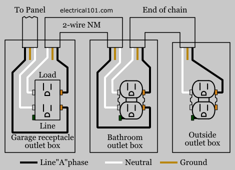
Below mentioned wiring diagram shows a single GFCI outlet connected with the multiple outlets. It means all the connected loads to the load terminals of.
 Wiring Multiple Outlets With A Gfi Wiring Diagram Overview Wires Shock Wires Shock Aigaravenna It
Wiring Diagram for Gfci and Light Switch wiring diagram is a simplified up to standard pictorial representation of an electrical circuit.
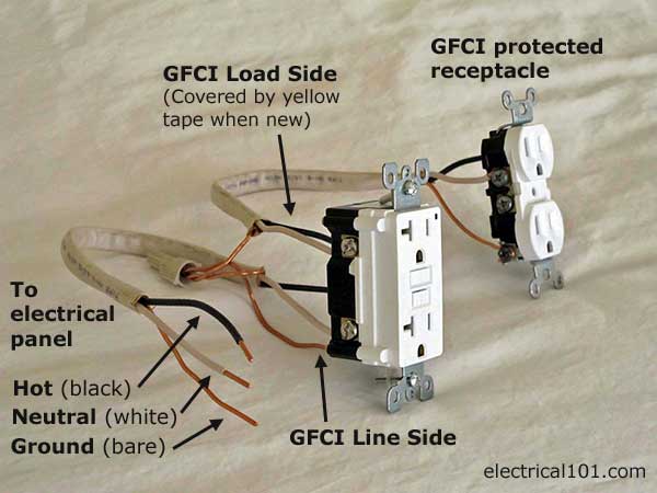
Wiring a gfi. This should go without saying but always cut power to the circuit and verify with a circuit tester before replacing an outlet. The line connection is used for all GFCI outlet installations. You can always replace a standard receptacle with a GFCI receptacle.
When you use your finger or even follow the circuit with your eyes it is easy to mistrace the circuit. Wiring a Two Poles GFCI Circuit Breaker The following wiring shows an ordinary outlet has been wired and protected through a double pole GFCI circuit breaker. The circuits hot wire typically.
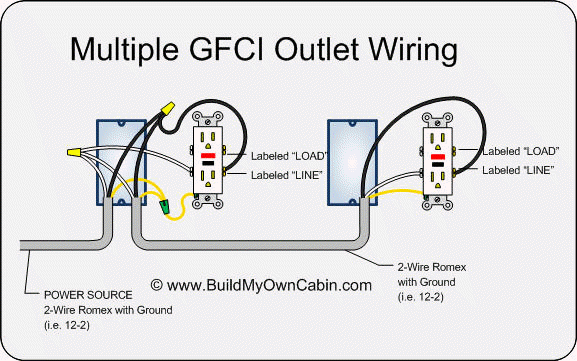
You can wire a single GFCI with multiple outlets using the 2 wires cables multiple outlets and GFCI. GFCI Outlet Wiring Method. In this GFCI outlet wiring and installation diagram the combo switch outlet SPST single way switch and ordinary outlet is connected to the load side of GFCI.
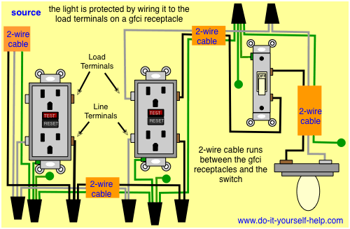
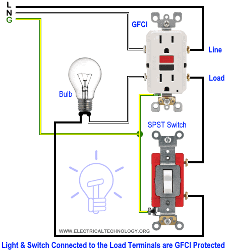
This diagram illustrates wiring a GFCI receptacle and light switch in the same outlet box a common arrangement in a bathroom with limited space. GFCI is a ground fault circuit interrupter. GFI is an ground fault interrupting outlet.
You wiring it up exactly the same. Wiring a GFCI Outlet and a Light Switch. The wire that shows 120vac is the hot from the panel this is the wire cable you want on the line side and the other wirecable on the load side then all the down line outlets or devices would be GFCI protected.
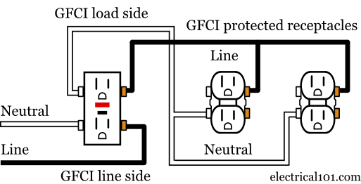
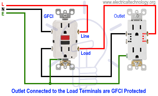
The source to the outlet is connected to the LINE terminals on the gfci. If installing a GFCI on an ungrounded circuit refer to the manufacturers instructions. Illustrated Guide for Wiring a Single GFCI Receptacle Outlet typically used as Bathroom GFI Kitchen GFI Outside GFI and Garage GFI Outlet.
They should be labeled no equipment ground until your 3 wire upgrade is complete. This wiring provides single-location gfci. Youll have to use that single GFCI as the source and then connecting the rest of the outlets using the same load and line terminals.
Wiring a GFCI Outlet with a Light Switch and Protected Receptacle. Electrical Wiring a Single GFI Outlet for Home Safety The wire leading to this location may be an extension from another branch circuit or it could be a single circuit being served from a panel or sub-panel. A single trick that We 2 to print out exactly the same wiring plan off twice.
Attach outgoing wires to outlets downstream to terminals marked load. Wiring a GFCI Outlet with Combo Switch Outlet Receptacle Light Switch. The LOAD terminals are connected to.
Just so where does the red wire go on a GFCI outlet. It shows the components of the circuit as simplified shapes and the capacity and signal friends in the midst of the devices. Same like above wiring diagram for 1-Pole GFCI CB the builtin white wire on the back side.
The built-in switch controls an unprotected light fixture on a separate electrical source. How to Wire a GFCI Outlet in an older home that does not have a ground wire and still have protection against ground faults that can cause electric shock. GFCI is a ground fault circuit interrupter.
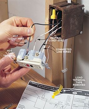
The hot source is spliced to the LINE terminal on the receptacle and to one terminal on the light switch. Carefully touch the black probe of the voltage tester to the metal box or bare copper ground wire. Photos show Step-By-Step Basics Including attaching wires to the GFI Outlet on the line side of the back of the receptacle.
When wiring a gfi outlet you will be attaching the wiring to the LINE area of the receptacle. The neutral and ground wires are spliced together and run to each device in the circuit. Simple Replacement of a Traditional Receptacle.
When wiring a GFCI or AFCI receptacle its important to connect incoming wires from the power source to the terminals marked line on the back of the receptacle.
 Gfci Wiring Diagram For Dummy S Universal Wiring Diagrams Device Verify Device Verify Sceglicongusto It
 Gfci Load Wiring Electrical 101
 Gfci Load Wiring Electrical 101
Gfci Load Wiring Electrical 101
 Wiring A Gfci Outlet With Diagrams Pro Tool Reviews
 Wiring Multiple Gfci Outlets
 Gfci Receptacle Wiring Universal Wiring Diagrams Symbol Words Symbol Words Sceglicongusto It
 How To Install Gfci Receptacle Outlets Diy Family Handyman
 Wiring Multiple Outlets With A Gfi Wiring Diagram Overview Wires Shock Wires Shock Aigaravenna It
 How To Wire A Gfci Outlet Gfci Wiring Circuit Diagrams
 How To Wire A Gfci Outlet Gfci Wiring Circuit Diagrams
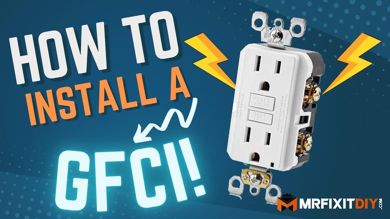 How To Install A Gfci Outlet Youtube
 Wiring A Gfci Outlet With Diagrams Pro Tool Reviews
 Gfci Receptacle Wiring Universal Wiring Diagrams Symbol Words Symbol Words Sceglicongusto It
Comments
Post a Comment